My initial relationship with the molar flowform was one of love/hate, that is until I learned that they are not trimmed with the bridles but small darts in the front of the profiles.
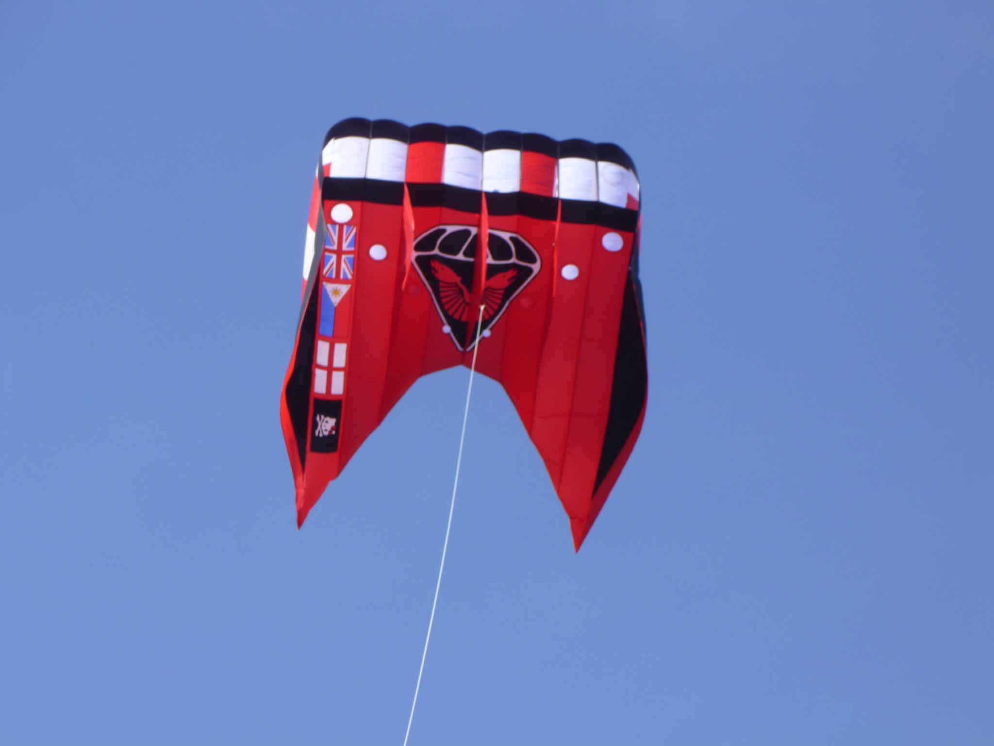
My first pilots were based on the plans available on-line for the Peter Lynn Pilot, however whilst they can be for the most part very stable, they do have a tendency to spin out under certain conditions. Whilst this not a huge issue when flying on one’s own, on a crowded show field having your pilot suddenly describe a huge loop in the sky can cause havoc as it takes out not just your display but that of many other flyer’s, so when I embarked on making Hello Kitty back in 2010, and needed a pilot with greater lifting capacity I decided on a 7m2 molar flowform based on Harald Prinzler’s FF04A patterns having seen how stable molar flowforms could be in comparison to parafoils and particularly so molar flowforms.

Formally recorded as my MK-I and more commonly known as the ‘Kitty Lifter’ this kite was built to FF04A patterns. Whilst it flies beautifully in right wind it has one major problem that is not intrinsic to the design but down to my construction, namely that it is too heavy being built of 56gsm fabric with the result that it has a very small window of wind speeds. It’s weight means that it needs about 14mph winds to fly with any power and initially had a pronounced lean to the left at winds of 18mph or more. It was in trying to correct this lean and constant referral to the information on Haralds website, that I learned that molar flowforms are immune to variations the lengths of the bridle legs but respond well to small adjustments the height of the leading edges of the profiles: where small adjustments to the legs of a parafoil or powersled bridle can have a large effect, several centimetres can be taken out of a flowform bridle leg with little or no effect on the flight characteristics of a flowfrom (this is great news when doing quick repairs on the flying field but a pain when trying to trim out a lean). So rather than trimming the bridle to correct a flight issue. Once adjusted the upper end of the wind range for this kite increased significantly. However during construction and over season of flying I discovered a couple of issues:
- whilst having parallel sided upper and lower skin sections makes them simple to layout and cut, the compound curves of the upper skin mean that the lengths of the upper and lower skin trailing edges don’t match and fabric has to be lost through the use of darts or gained by stretching on the bias.
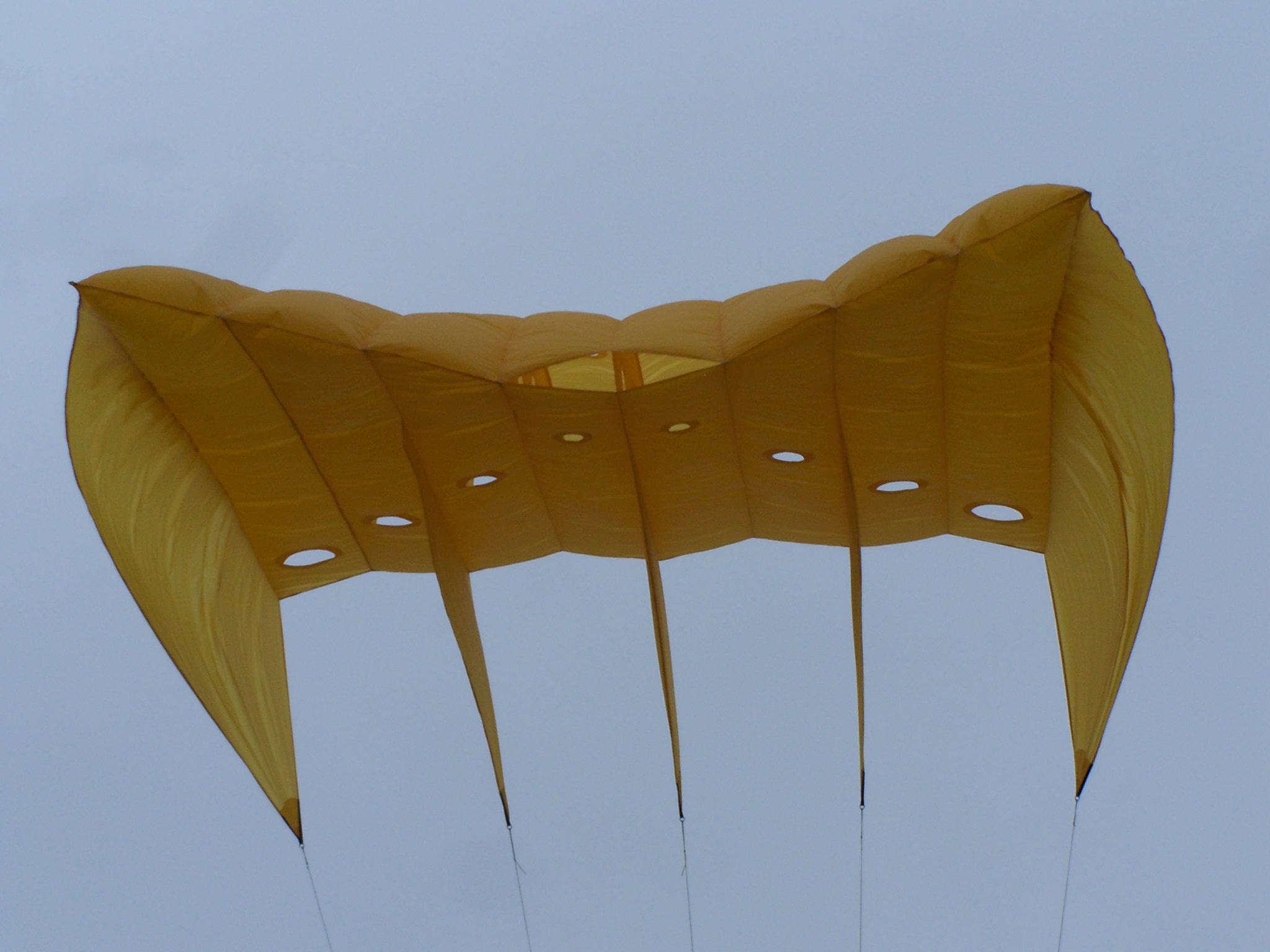
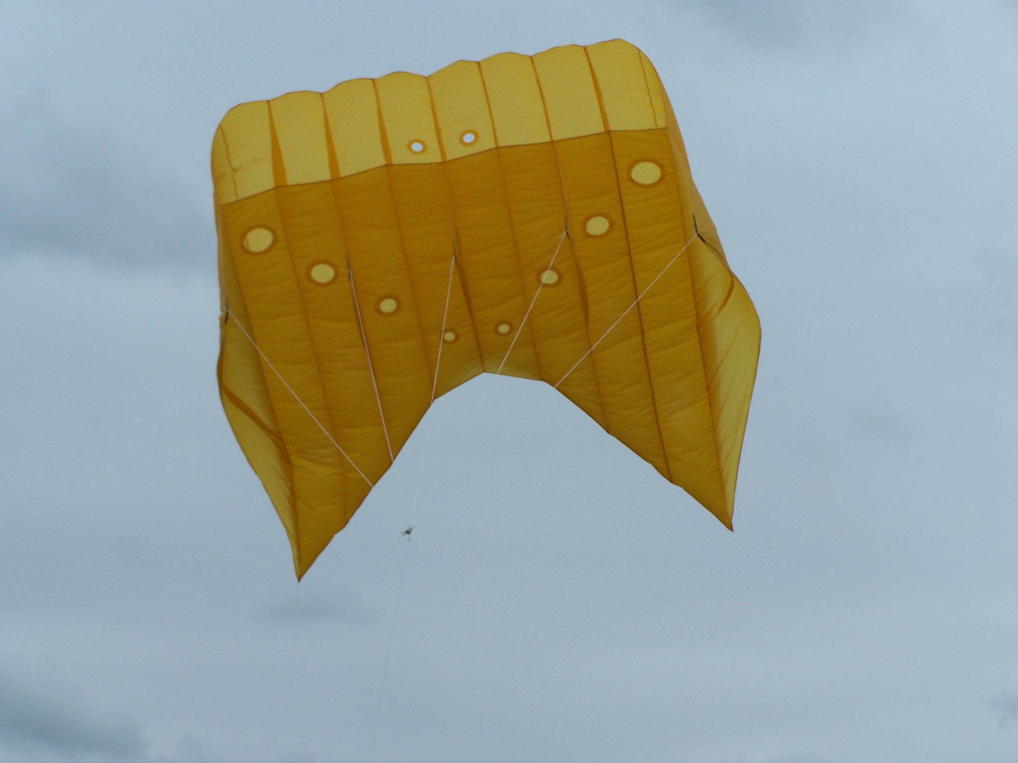
In 2012 in order to cure some of the issues with the MK-I the MK-II (AKA ‘Big Yellow’) was built again at 7m2. The key changes incorporated into the MK-II were a new upper skin and sand drains in the lower skin. To achieve the changes in the upper skin a 3D CAD model was constructed, thus resulted in hockey stick shaped upper panels. Being built from 40gsm fabric the MK-II will fly from about 3mph and will start lifting at 6-7mph and as a result has become my major workhorse.
2012 also saw the build of several MK-IIIs in various sizes (1.6m2, 2.7m2, 4.8m2) predominantly designed and built for KAP work the MK-III has a altered profile to compensate for the reduced sizes.
Whilst the MK-II remained my workhorse, it still suffered from two key issues which I have seen with other flowforms that have a common ancestry:
- at high winds, the upper skin starts to crease just behind the leading edge and propagating from either side profile, this results in an ever increasing lean.
- at low winds the kite has a tendency to irrecoverably collapse
Over the ensuing two and a bit years a conversation ensued with the Phil ‘The Flames’ Scarfe, covering the various aspects of the flowforms and the history and dubious claims around the design elements plus possible solutions to the various issues. The conversation saw the creation of the MK-IV, MK-V and MK-VI which never progressed beyond 3D models but culminated in the MK-VI. Sadly Phil passed away before he was able to see the culmination to this conversation. Rather than small incremental changes because the MK-IV, MK-V and MK-VI never saw the light of day the MK-VII is quite a major step change:
- Lower Skin
-
Explanatory documents suggest that the holes in the lower skin are to promote laminar flow and that air is sucked into the body of the kite. If you read scientific papers on promoting laminar flow on non-laminar flow aerofoils, it is very much the case that air is drawn in through suction holes in the lower surface and bled out through holes in the upper surface, however this movement is via a sealed ducting within the wing not a wing that is being inflated by the wind. Our conclusion was that rather than allowing air to be drawn in through the holes it would be expelled adding to the speed of deflation should the wind drop and that they were far more likely to be ‘patent’ holes included to overcome patent restrictions than to promote laminar flow. As a result they were dropped from the MK-VII
- Profile Holes
-
The large profile holes are described as promoting cross flow between the eight chambers and balancing the internal pressures, however since their cross sectional area is larger than the size of the leading edge intake the cross flow is so great as to allow the rapid deflation of the kite should the wind drop and a cell start to collapse. As a result the holes were dropped from the MK-VII internal profiles, which were instead sectionalised and assembled to form a series of vertical slots. The idea being that the slots would allow pressure equalisation but at reduced rate slowing any deflation.
- Upper skin
-
As with the holes in the lower skin, the holes in the upper skin are reputedly there to promote laminar flow, however based on research papers, the holes are the wrong size and in the wrong place. The holes were thus replaced by two strips of much smaller holes running in lines across the upper skin, the first line being parallel to and 100mm back from the leading edge and the second at 67% of the chord of the aerofoil.Finally the skin was folded back at the leading edge and continued into the cells where it was supported by a series of supplemental profiles but left open at the back. The theory being that the pressure inside the cell would cause the leading edge to inflate an prevent the creasing from occurring at high wind speeds.
Despite being made from some of the worst fabric I have had (it was cheap) the MK-VII or ‘Big Blue’ has performed well; the turn back on the leading edge does appear to prevent the folding seen at high wind speeds on previous designs plus it keeps the leading edge very flat. The change to slots over holes appears to slow deflation as intended with the rsult that rather than collapsing and falling unrecoverably out of the sky the MK-VII floats down full inflated and is straightforward to recover.